Plc-5 2 Slot Addressing

- Plc 5 Slot Addressing
- Plc-5 2 Slot Addressing Machines
- Plc-5 2 Slot Addressing Tool
- Plc-5 2 Slot Addressing Machine
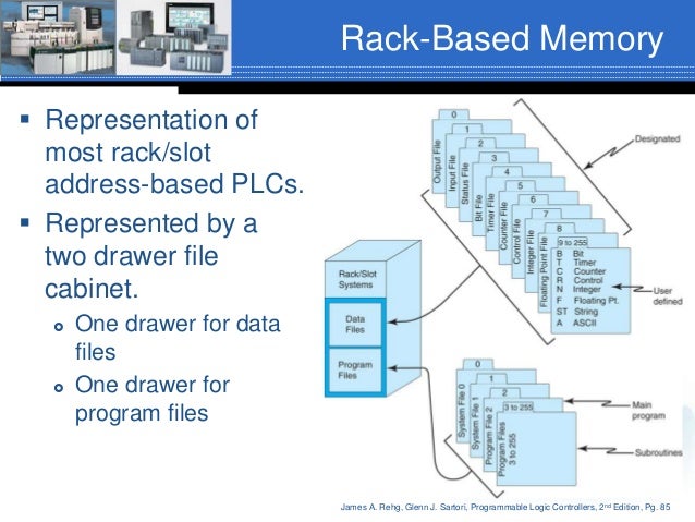
2 Maximum I/O possible using 16-pt modules with 2-slot addressing or 32-pt modules with 1-slot addressing. Modules must alternate input/output in the chassis slots. Hardware Components. Micro/SLC-500/PLC 5 Addressing Formats. The general format of value names for data from the listed controllers matches the naming convention used by the programming software. The format is shown below. The parts of the name shown in in square brackets are optional. Number of input and output points they can service. Large systems can have greater than 120 000 I/O's and, as the systems become larger, the programming, memory and communication capabilities also increase.

We strongly recommend referring below post as a prerequisite of this.
Hashing Set 1 (Introduction)
Hashing Set 2 (Separate Chaining)
Open Addressing
Like separate chaining, open addressing is a method for handling collisions. In Open Addressing, all elements are stored in the hash table itself. So at any point, the size of the table must be greater than or equal to the total number of keys (Note that we can increase table size by copying old data if needed).
Insert(k): Keep probing until an empty slot is found. Once an empty slot is found, insert k.
Search(k): Keep probing until slot’s key doesn’t become equal to k or an empty slot is reached.
Delete(k): Delete operation is interesting. If we simply delete a key, then the search may fail. So slots of deleted keys are marked specially as “deleted”.
The insert can insert an item in a deleted slot, but the search doesn’t stop at a deleted slot.
Open Addressing is done in the following ways:
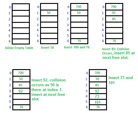
a) Linear Probing: In linear probing, we linearly probe for next slot. For example, the typical gap between two probes is 1 as taken in below example also.
let hash(x) be the slot index computed using a hash function and S be the table size
Let us consider a simple hash function as “key mod 7” and sequence of keys as 50, 700, 76, 85, 92, 73, 101.
Challenges in Linear Probing :
- Primary Clustering: One of the problems with linear probing is Primary clustering, many consecutive elements form groups and it starts taking time to find a free slot or to search an element.
- Secondary Clustering: Secondary clustering is less severe, two records do only have the same collision chain(Probe Sequence) if their initial position is the same.
b) Quadratic Probing We look for i2‘th slot in i’th iteration.
c) Double Hashing We use another hash function hash2(x) and look for i*hash2(x) slot in i’th rotation.
See this for step by step diagrams.
Comparison of above three:
Linear probing has the best cache performance but suffers from clustering. One more advantage of Linear probing is easy to compute.
Quadratic probing lies between the two in terms of cache performance and clustering.
Double hashing has poor cache performance but no clustering. Double hashing requires more computation time as two hash functions need to be computed.
Performance of Open Addressing:
Like Chaining, the performance of hashing can be evaluated under the assumption that each key is equally likely to be hashed to any slot of the table (simple uniform hashing)
Plc 5 Slot Addressing
References:
http://courses.csail.mit.edu/6.006/fall11/lectures/lecture10.pdf
https://www.cse.cuhk.edu.hk/irwin.king/_media/teaching/csc2100b/tu6.pdf
Please write comments if you find anything incorrect, or you want to share more information about the topic discussed above.
Attention reader! Don’t stop learning now. Get hold of all the important DSA concepts with the DSA Self Paced Course at a student-friendly price and become industry ready.
Recommended Posts:
Improved By : PulkitGoel2, shubham_singh, himanshu_shekhar
Plc-5 2 Slot Addressing Machines
There are a number of addressing schemes used by PLC manufacturers. Let’s take a quick look at how memory locations (including hardware I/O) are accessed with RSLogix 500. Along the way, let’s define some terms.
INSTRUCTION – RSLogix’s command language is comprised of “instructions”. An XIC (it looks like a normally open contact –] [– ) is an instruction. A timer is an instruction. A few of the most common instructions are described below.
BIT – an address within the PLC. It can be an input, output or internal coil, among others.
In RSLogix, there are a couple of ways to show the address of a bit. The default is:
[type]:[word]/[bit]
For example, an address that references an output of a MicroLogix 1100 is O:0/0. That is:
O:0/5 means that it is a physical output.
O:0/5 means that it uses Slot 0 (in the case of the 1100, this output is onboard)
O:0/5 means that it is the fifth output on the PLC.
By the way, don’t get the capital “O” confused with a zero.
RUNG – A section of the PLC ladder program that terminates in an output function of some type. Just like in an electrical ladder diagram, a rung has some type of output that is turned on or turned off by the preceding entities in the rung. The first rung in a ladder program is always 0000.
HARDWIRED INPUT – a physical connection to the PLC from an input device (switch or sensor, etc.).
Allen-Bradley uses the capital letter “I” to designate a hardwired input. An address that describes an input on an SLC 500 is I:4/0.
Similar to the output structure,
Plc-5 2 Slot Addressing Tool
I:4/0 means that it is a physical input.
I:4/0 means that it uses Slot 4 (the 5th slot in the rack).
I:4/0 means that it is the first input on the card.
Don’t get the capital “I’s” confused with ones.
HARDWIRED OUTPUT – a physical connection from the PLC to an output device (relay or pilot light, etc.) As was said above, an address that references an output of an SLC 500 is O:5/0.
INTERNAL COIL
This is a programmable bit used to simulate a relay within the PLC. The internal coil has no connection to the outside world. It does not connect to an output card. Internal coils are used to store information. The “contacts” of this “relay” can then be used multiple times in other parts of the program.
In RSLogix, the “B3” (binary) file is commonly used for all the internal coils. There are many other words in other files that have bits you can use as internal coils, but we are going to stick with the B3 file for our application.
B3:0/0 means that it references an internal Binary file
B3:0/0 means that it uses the first word in the table
B3:0/0 means that it is the first bit in the word.
Note that, unlike the Output and Input files, you have to use the file number in the address. In this case, the default file number is 3.
TIMER
A timer is a programmable instruction that lets you turn on or turn off bits after a preset time.
The two primary types of timers are TON for “timer on delay” and TOF for “timer off delay”.
Timers in A-B SLC and MicroLogix processors use file 4 for their timers.
T4:0 means that it references an internal Timer file
T4:0 means that it uses the first timer in the table
The address T4:0 simply refers to the timer. Each timer has bits that turn on after the timing function is complete. You can address this bit by simply putting a “/DN” after the timer address. DN stands for “done”.
For example, if timer T4:0 is a TON (timer on delay), then the bit T4:0/DN will turn on after the timer has reached its preset value.
COUNTER
A counter is a programmable instruction that lets you turn on or turn off bits after a preset count has been reached.

There are different types of counters available in the RSLogix, but the CTU (counter up) instruction covers everything we will talk about here.
Counters in A-B SLC and MicroLogix processors use file 5.
C5:0 means that it references an internal Counter file
C5:0 means that it uses the first counter in the table
The address C5:0 simply refers to the counter. Each counter has bits that turn on after the counting function is complete. You can address this bit by simply putting a “/DN” after the counter address. DN stands for “done”.
For example, if counter C5:0 is a CTU (counter up), then the bit C5:0/DN will turn on after the counter has reached its preset value.
–] [– Normally Open Contact
When used with a hardwired input, this instruction is off until there is a voltage applied to the input. The bit address then goes high, or on, and the instruction becomes “true.” It works the same way when it has the same address as an internal coil, except that the coil must be turned on by logic in the program.
Allen-Bradley calls these normally open contacts “XIC”, or “eXamine If Closed” instruction.
An XIC instruction can reference a hardwired input, a hardwired output, an internal coil or a timer done bit, among others.
–]/[– Normally Closed Contact
This is an inverted normally open contact.
When used with a hardwired input, this instruction is “true” until there is a voltage applied to the input. It then goes low, or off, and becomes “false.”
It also can be used with an internal coil, becoming true when the coil is off and becoming false when the coil is on.
Allen-Bradley calls these normally closed contacts “XIO”, or “eXamine If Open” instructions.
-( )- Output Coil
When used with a hardwired output, this function is off until the logic in the program allows it to turn on. It then becomes “true”, and will energize the device that is wired to the respective output.
If it is used as an internal coil, it will toggle the instructions associated with it. That is, it will close a normally open instruction and open a normally closed instruction.
Allen-Bradley calls these outputs “OTE”, or “OutpuT Energize”.
An OTE may be used with a hardwired output or an internal coil.
Plc-5 2 Slot Addressing Machine
TRUE – A state that indicates an instruction is allowing logic to “flow” through it.
Also, if the logic in a rung turns on the output of the rung, then the rung is said to be true.
FALSE – Without stating the obvious, this is the opposite of true.

Excerpted from PLC Programming with RSLogix 500